

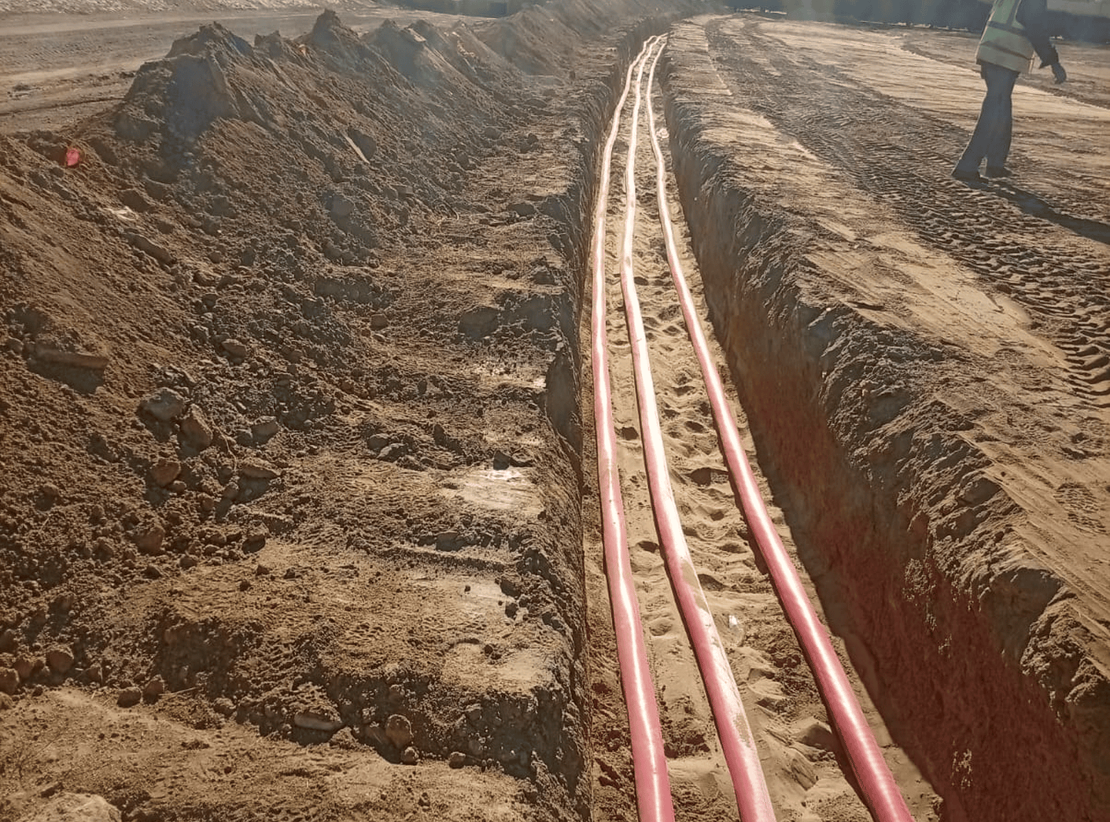
Ground Grid and Earthing
Substation ground grid and earthing design is vital to ensure human safety and equipment protection during ground faults. MEPCO designs and evaluates earthing networks, calculating Ground Potential Rise (GPR), mesh voltages, step and touch voltages, and grid resistance in strict compliance with IEEE 80-2013 and IEC standards.

Figure 1: High-voltage transformer grounding conductors and substation earthing grid connections.
Technical Scope & Engineering Capabilities
MEPCO Engineering Projects brings specialized domain knowledge, rigorous modeling standards, and practical site experience to every assignment. Our scope covers:
- Soil Resistivity Interpretation: Modeling multilayer soil structures (Wenner four-pin test data inversion) to determine apparent soil resistivity and reflection factors.
- Fault Current Division & Split Factor: Calculating the fraction of fault current flowing into the earth grid vs. overhead shield wires/cable sheaths (split factor \(S_f\)).
- Tolerable Touch & Step Voltage Thresholds: Calculating maximum permissible body touch and step voltages based on 50 kg or 70 kg body weight and surface gravel resistivity.
- Mesh & Step Voltage Calculations: Computing actual mesh voltages (\(E_m\)) and step voltages (\(E_s\)) under maximum line-to-ground fault conditions.
- Ground Potential Rise (GPR) & Grid Resistance: Calculating total grid resistance (\(R_g\)) and Ground Potential Rise to evaluate telecommunication isolation hazards.
- Conductor & Ground Rod Sizing: Sizing copper earthing conductors against short-circuit thermal fusing per IEEE 80 formulas.
Software Platforms & Computational Tools
Primary Tool: ETAP Ground Grid Systems (GGS) Module (IEEE 80 & Finite Element Method).
Applicable Standards & Grid Codes
Substation Grounding: IEEE 80-2013 (IEEE Guide for Safety in AC Substation Grounding).
Testing & Safety Standards: IEEE 81 (Guide for Measuring Earth Resistivity and Ground Impedance), IEC 60479-1.
Methodology & Project Delivery Workflow
Our engineering delivery aligns with MEPCO’s structured 6-stage project execution framework, ensuring quality throughout input verification, design modeling, and client handover:
- Stage 01 — Scope & Criteria Definition: Establish study boundaries, utility tie-in data, single-line diagrams, and client objectives.
- Stage 02 — Data Audit & Modeling Assumptions: Collect, verify, and validate manufacturer datasheets, impedance tolerances, and site operating configurations.
- Stage 03 — Simulation Model Development: Build detailed, validated mathematical digital models in specialized power software.
- Stage 04 — Computational Analysis & Verification: Execute base-case and contingency scenarios, conducting rigorous internal peer reviews.
- Stage 05 — Client Review & Approval: Present study findings, address technical comments, and participate in technical clarification sessions.
- Stage 06 — Final Handover: Deliver formal certified engineering reports, executive summaries, and native simulation model files.

Figure 2: Substation gravel surface layer and buried copper conductor mesh designed to limit step and touch potentials.
Completed Project References (From MEPCO Profile)
Selected project assignments delivered by MEPCO demonstrating our technical execution and regional client trust:
| Project Name | Client / Authority | Location | Tools / Mode | Scope Executed |
|---|---|---|---|---|
| Utility Substation Earthing Designs | Egyptian & Saudi Utility Authorities | Egypt / KSA | ETAP GGS | Ground Grid Design, Step & Touch Potential Calculations per IEEE 80, Soil Resistivity Modeling. |
| Industrial Plant Earthing Systems | Petrochemical & Heavy Industrial Facilities | Regional | ETAP GGS | Earthing Mesh Optimization, GPR Mitigation, and Telecommunication Isolation. |
Key Engineering Deliverables & Outputs:
- Comprehensive Substation Grounding Study Report with soil multilayer models.
- Tolerable vs. Actual Touch and Step Voltage Comparison Charts proving safety margins.
- Ground Grid CAD Layout Drawings detailing conductor grid spacing, ground rod locations, and test pits.
- Conductor Sizing and Exothermic Welding Specification Sheets.
- Native ETAP GGS calculation model.
Inquire About This Service
Contact MEPCO’s engineering team for technical proposals, study scope definition, or project consultations:
Email: m.khaled@mepco-tds.com | Phone: +20 11 2696 7082 | HQ: 5 Al-Ibrahimia Street, Cairo, Egypt